How Do Card Socket Connectors Drive Innovation in Card Reader Design?
- Share
- publisher
- Moarconn
- Issue Time
- Mar 15,2025
Summary
There is a condensed analysis of Card socket connectors' key applications and technical features.
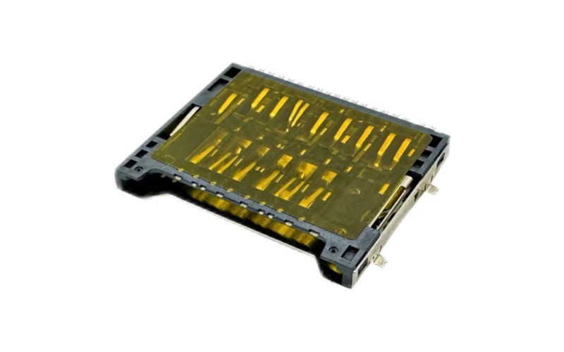
Card socket connectors are the part of a card reader that turns a piece of plastic with a chip in it into a working interface. They carry power and data, hold the card in position, and tell the host when a card has arrived. Get any of those three wrong and the reader fails in a way the customer notices — dropped transfers, cards that are not detected, or a slot that stops accepting cards after a year of daily use.
What the Socket Contributes to a Reader
Three functions, and they fail independently. Electrical: a set of spring contacts with low, stable resistance, plated to survive thousands of wipes. Mechanical: guidance so the card enters square, a latch or friction hold so it stays seated, and an eject mechanism if the reader is user-facing. Signalling: a card-detect contact so the controller knows when to start an initialisation sequence instead of polling.
Most reader designs over-invest in the first and under-specify the other two. A reader with excellent contacts and no card-detect line works on the bench and drains a battery in the field; a reader with a good latch and marginal plating passes production and returns in year two.
Contact Design: Landing vs Sliding
Two contact architectures dominate, and they suit different products. Sliding (wipe) contacts — the type used in SD and microSD sockets — drag across the card pads as it enters. The wipe cleans the surface, which is why these sockets tolerate dusty environments, but it also wears the plating, so cycle life depends on gold thickness. Landing contacts, used in IC card and bank-card readers, stay clear of the card until it is fully seated, then press down on the chip. There is almost no wipe, so the cycle life can be an order of magnitude higher, at the cost of a more complex mechanism and a taller housing.
Practical consequence: for a memory-card reader that will see thousands of insertions, specify gold thickness before you specify mechanism. For a chip-card reader that must survive a million transactions, landing contact is the only sensible architecture. Our guide to IC card connectors and IC sockets covers the second case in detail.
Card Detection and Hot-Swap
A reader that supports hot-swap needs two things from the socket: a card-detect contact, and a contact geometry where ground mates first and breaks last. Without detection the host has to poll the interface, which costs current and adds enumeration latency on every wake. With it, the controller can stay idle until the switch closes, then run a clean power-up sequence.
Verify the sequence rather than assuming it. Ask for the contact mating order or test it with a sacrificial card: GND should connect before any signal pin, and the detect line should change state before the data lines are driven. A socket that detects the card and drives DAT0 in the same millisecond will produce intermittent enumeration failures that look like a firmware bug.
Standards a Reader Has to Meet
Which standards apply depends on what the reader reads. Memory-card readers follow the SD family — SD 3.0 for UHS-I speeds, and the later revisions where SD Express is required — plus USB-IF specifications on the host side if the reader is a bus-powered peripheral. Chip-card readers follow ISO 7816 for the contact layout and, for payment terminals, EMV for the transaction layer. Industrial readers add IEC environmental testing; automotive readers add ISO 16750-3 vibration evidence.
Choosing the socket is where these standards become concrete. A UHS-II or SD Express reader needs a socket with a second contact row and a PCB that can carry a controlled-impedance pair to it; a UHS-I reader does not, and paying for the second row adds cost and layout constraint for no benefit.
Consumer Readers vs Industrial Readers
A consumer reader is judged on height and feel: 1.28 to 1.6mm microSD sockets, push-push mechanisms, cosmetic consistency from the first insertion to the thousandth. An industrial reader is judged on years in service: hinge or push-pull mechanisms with exposed contacts that can be inspected and cleaned, wide temperature range, and plating thick enough that contact resistance still holds at 30mΩ after a decade of monthly card swaps.
Both are legitimate designs, and the mistake is to specify one as if it were the other. A consumer socket in an outdoor enclosure usually passes the prototype and fails the third winter; an industrial socket in a phone adds height and cost for durability the product will never use.
Design Choices That Decide Reader Life
- Plating thickness. 0.025µm gold over nickel is the floor for a part rated to 10,000 cycles at 30mΩ or less. Half that plating passes incoming inspection and drifts in year two.
- Coplanarity. ±0.05mm on MOARCONN parts against the ±0.10 mm common in the industry, with 0.05mm max full-area flatness. This decides first-pass solder yield on a thin reader PCB.
- ESD path. The card slot is an aperture to the outside world. Ground the shell at every mounting tab and route the card signals through a TVS array close to the connector.
- Retention under shock. A drop test is a retention test, not a contact test. Specify the retention force, not just the mechanism.
Where Readers Are Going
Three shifts are visible in current designs. Readers are being absorbed into USB-C hubs, where the card slot is one function among many and the constraint is total height and PCB area. SD Express is arriving in imaging and industrial products, which pushes the second contact row into mid-range readers. And in sealed IoT devices the reader disappears entirely — a soldered MFF2 SIM and embedded flash replace the socket, because a mechanical interface is a failure mode that a remote deployment cannot afford.
MOARCONN supplies card connectors for card readers across SD, microSD and Nano SIM formats, with 141 models across 13 series, 0 MOQ, 7-day sampling and a 25-day development cycle for custom housings.
Card Reader Design FAQ
Do I need a second contact row for my reader?
Only if you need UHS-II or SD Express speeds. A UHS-I reader at up to 104MB/s works with a single-row socket, and adding the second row adds cost, height and a controlled-impedance layout constraint. Decide the interface before the PCB is cut; retrofitting the second row is a respin.
Why does a reader fail to detect a card that works elsewhere?
Usually the card-detect switch, not the data contacts. The detect contact has its own spring and its own wear rate, and it is the part most often omitted from a cycle-life specification. Check whether the switch is normally-open or normally-closed, confirm the housing lets the card travel far enough to actuate it, and measure the switch resistance after cycling.
Is a hinge socket better than push-push for an industrial reader?
For most industrial readers, yes. A hinge exposes the contacts for cleaning and inspection, has no internal ejector cam to jam, and gives a visible confirmation that the card is latched. Push-push is better where the reader is user-facing and the card must be inserted with one hand.
MOARCONN Quality Anchors
Every MOARCONN card socket connector is validated to 10,000 mating cycles (tested to GB/T 5095.7-1997; over 2× the 3,000–5,000 cycles common in the industry), operates from -45°C to 80°C, and ships with contact resistance ≤30mΩ thanks to ≥0.025µm gold-plated phosphor-bronze terminals. IATF 16949 certified production supports 0 MOQ orders with 7-day sampling and a 25-day development cycle — backed by in-house mold, stamping and injection molding factories and 32 granted patents.