How can you select high - performance card socket connectors without this concise guide?
- Share
- Issue Time
- Mar 7,2025
Summary
High-Performance Card Socket Connector Selection Guide
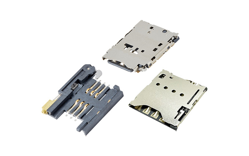
Selecting a card socket connector is a five-step decision, and most projects get it wrong at step one by starting from a supplier catalogue instead of from the interface. The sequence below moves from electrical requirements to supply, with the specification to write at each step and the way to verify it.
Step 1: Fix the Electrical Requirement
Start from the interface speed, because it decides the contact architecture. A UHS-I card interface runs up to 104MB/s single-ended and needs 50Ω single-ended impedance with a continuous reference plane; UHS-II and SD Express add a second contact row carrying a differential pair, and no amount of layout tuning will substitute for the missing row. Contact resistance should be 30mΩ or less for a card socket — a generic "under 100mΩ" figure belongs to power connectors, not to a 200MHz signal path.
Shielding is part of the electrical requirement, not a separate topic. A metal shell grounded at multiple points reduces radiated emissions and improves crosstalk rejection between adjacent contacts; a shell grounded at one corner behaves like an antenna.
Step 2: Specify Materials and Plating
Contacts are phosphor bronze with gold over nickel. The number that matters is the gold thickness: 0.025µm is the practical floor for a part rated to 10,000 cycles at 30mΩ or less, and thinner plating trades a fraction of a cent for a field-return problem once the nickel barrier is exposed. Housing material follows the process — LCP where the wall is thin and the part goes through reflow, PBT where cost dominates and the wall is generous.
Temperature rating is a material decision as much as a test result. A card socket rated to 80°C covers automotive cabin and industrial cabinet environments; a part rated to 60°C is a consumer part and should not be specified into a device that sits in a metal enclosure outdoors.
Step 3: Choose the Mechanism and Mounting
Mechanism follows duty cycle. Push-push (self-eject) for user-facing products where the card is swapped often; push-pull for parts fitted once, where the simpler mechanism is also the more reliable one; hinge or flip-lock where the contacts must be inspectable and cleanable. Every mechanism needs two numbers in the drawing: the insertion/extraction force window, and the cycle rating at that force.
Anti-misinsertion is a housing feature, not an electrical one: a keyed slot, a chamfered corner, an asymmetric body. Mounting is SMT or through-hole, top or reverse mount. Reverse mount saves board area at the cost of a PCB cut-out and tighter placement tolerance, which is a reasonable trade in a phone and a poor one in an industrial controller.
Step 4: Match the Environmental Grade
Write down the four environmental numbers before you compare parts: operating temperature range, vibration profile, humidity or damp-heat requirement, and any sealing requirement. Automotive programs should ask for ISO 16750-3 vibration evidence rather than a generic "vibration tested" statement, because the profile matters more than the pass mark. Industrial equipment in dusty or oily environments benefits from a hinge mechanism with exposed contacts; sealed consumer products need the opposite.
For outdoor and marine installations, salt-spray resistance becomes a plating question, and the answer is more gold or a nickel barrier — not a coating.
Step 5: Cost and Supply
Compare quotes on five numbers, not on price: plating thickness and under-plate, coplanarity tolerance, rated cycles at the quoted force window, sample lead time, and whether the supplier owns its tooling. A 30% price difference almost always traces back to one of those five.
Supply strategy matters as much as unit cost. A supplier with a broad catalogue can adapt an existing tool instead of opening a new mold, which is the difference between a 25-day development cycle and a three-month program. MOARCONN runs 141 card socket models across 13 series, quotes 0 MOQ with 7-day sampling, and supports custom card socket connector requests on that timeline.
Selection Checklist
| Requirement | What to write in the spec | How to verify |
|---|---|---|
| Interface speed | UHS-I single row, or UHS-II / SD Express with second row | Eye diagram at the highest claimed mode |
| Contact resistance | 30mΩ max, gold 0.025µm min over nickel | Measure before and after 500 thermal cycles |
| Mechanical life | 10,000 cycles at the specified force window | Force curve across 20 cycles, then cycle test |
| Assembly | Coplanarity ±0.05mm after reflow | Measure on your own assembly, tail of panel |
| Environment | -45 to 80°C, ISO 16750-3 where applicable | Supplier test report, not a compliance sentence |
Card Socket Selection FAQ
Is a lower contact resistance always better?
Lower is better up to the point where the specification stops being meaningful. For a card socket, 30mΩ or less across the rated life is the practical target; chasing 10mΩ on a datasheet usually means the figure was measured dry and new. What matters is stability — the resistance at cycle 10,000 and at -45°C, not at the first insertion.
Do I need a shielded connector?
Yes if the interface runs above roughly 50MHz, or if the product must pass EMC with the card slot exposed. A metal shell grounded at multiple tabs is the cheapest effective shield. For a low-speed SIM interface inside a sealed enclosure, shielding adds cost without changing the result.
How do I choose between an existing model and a custom housing?
Start from the closest existing model and change the housing only if the height, the card path or the mounting cannot be met. With 141 models across 13 series, most requirements are a modification, and a modification keeps the 25-day development cycle instead of a new mold program.
MOARCONN Quality Anchors
Every MOARCONN card socket connector is validated to 10,000 mating cycles (tested to GB/T 5095.7-1997; over 2× the 3,000–5,000 cycles common in the industry), operates from -45°C to 80°C, and ships with contact resistance ≤30mΩ thanks to ≥0.025µm gold-plated phosphor-bronze terminals. IATF 16949 certified production supports 0 MOQ orders with 7-day sampling and a 25-day development cycle — backed by in-house mold, stamping and injection molding factories and 32 granted patents.