How to Install and Troubleshoot an SD Card Connector on PCB
- Share
- publisher
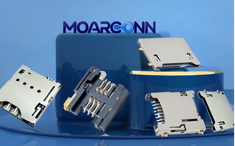
- MOARCONN
- Issue Time
- Jul 23,2025
Summary
Why Choose MOARCONN for Your SD Card Connector Needs?

Introduction: Why Proper SD Card Connector Installation Matters
SD card connectors are essential components in modern embedded systems, used to store firmware, log data, or expand memory. Yet improper layout or installation can lead to severe system instability, data loss, or even hardware failure.
As a leading manufacturer of SD card connectors, MOARCONN (www.moarconn.com) is committed to helping engineers design, install, and maintain highly reliable connector interfaces. In this guide, we share installation best practices and troubleshooting insights to optimize your PCB layout and connector reliability.
Step-by-Step Installation Guide for SD Card Connectors on PCB
1. Understand Connector Types
Standard SD, microSD, miniSD: Choose based on your space constraints and storage requirements.
Mounting style: Choose between push-push, push-pull, or hinged-lid types.
Tip: MOARCONN provides over 40+ models of SD and microSD connectors with customized mechanical locking options.
2. Pin Assignment and Schematic Considerations
Most microSD sockets use 8 contacts; standard SD cards use 9.
Include 10k pull-up resistors on CMD, DAT lines.
Use series resistors (~33Ω) on CLK to reduce EMI.
ESD protection is essential. Add TVS diodes on I/O lines to meet industrial standards.
3. PCB Layout Best Practices
Route data and clock lines with matched impedance (typically 50Ω single-ended).
Keep traces short and away from noisy power circuitry.
Place microSD connectors at the PCB edge, oriented to minimize routing complexity.
Include card detect and write-protect signals if supported by the host.
Common Issues and How to Troubleshoot
Even with proper design, SD connectors can fail due to mechanical wear, debris, or soldering faults.
1. No Detection or Intermittent Connection
Check solder joints on CMD, CLK, VDD lines under microscope.
Verify that the card-detect pin is wired and functioning.
Try cleaning the contact area with isopropyl alcohol.
2. Miswired Connector Fix (Case Study Inspired by hforsten.com)
If you’ve wired the footprint backwards, use an interposer PCB with pin remapping.
A level-shifter can be added to handle 3.3V ↔ 1.8V translation if needed.
3. Soldering and Reflow Issues
Use proper thermal profiles when reflowing SD connectors.
Avoid bridging on fine-pitch pins — use solder mask defined pads.

Why Choose MOARCONN for Your SD Card Connector Needs?
At MOARCONN, we specialize in precision-engineered card connectors, serving customers across telecommunications, automotive electronics, and industrial IoT sectors.
Key advantages of MOARCONN SD connectors:
1. 10,000+ insertion durability
2. Anti-misinsertion mechanical structure
3. Customizable pin count, height, and ejection mechanism
4. RoHS & REACH compliance
Conclusion
Whether you're designing a data logger, single-board computer, or consumer gadget, the SD card connector you choose — and how you install it — directly affects system reliability. By following proven layout practices and leveraging insights from real-world troubleshooting, your hardware can perform at its peak.
Looking for reliable SD card connectors?
Browse our full range at MOARCONN.com, or contact us for samples and technical support.