Why SD Card Connector Selection Matters
- Share
- publisher
- MOARCONN
- Issue Time
- Aug 14,2026
Summary
Learn how to choose the right SD Card Connectors for automotive, industrial, IoT, and consumer electronics applications.
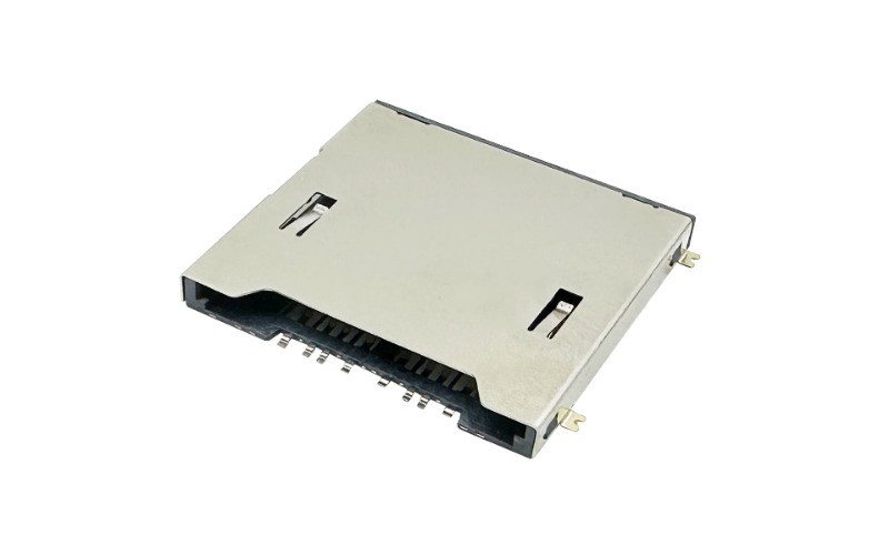
Why SD Card Connector Selection Matters
An SD card connector is more than a socket that holds a memory card. It is a critical electromechanical interface between the removable storage media and the host PCB, affecting electrical continuity, mechanical retention, signal integrity, serviceability, and long-term product reliability.
The right SD Card Connector can vary significantly depending on where and how the final electronic product will be used.
A compact consumer device may prioritize a low-profile design, easy card insertion, and a small PCB footprint. An automotive system may place greater emphasis on vibration resistance, shock tolerance, temperature stability, shielding, and secure card retention. Industrial equipment can require long service life and stable electrical contact under repeated mechanical and environmental stress, while an IoT product may require a combination of compact dimensions, reliable data transmission, and cost-effective integration.
Industry product and engineering references show that SD and memory-card connector selection involves mechanical configuration, card retention, mounting orientation, environmental requirements, and electrical performance—not simply choosing a connector based on card format.
For engineers, OEMs, and product designers, the most useful approach is therefore:
Application → Operating Environment → Design Requirements → SD Card Connector Configuration
This guide explains how to make that decision.
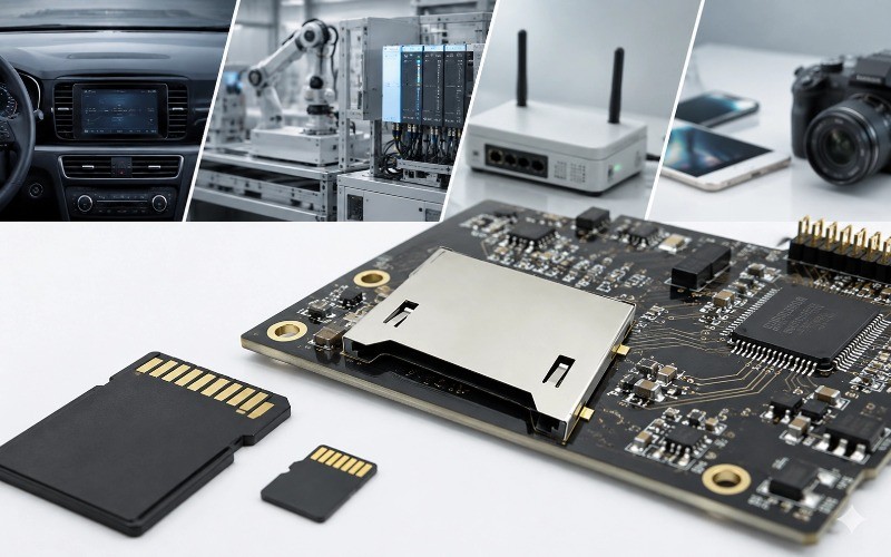
1. What Is an SD Card Connector?
An SD Card Connector is a mechanical and electrical interface that connects an SD memory card to a printed circuit board.
Its primary functions include:
Establishing reliable electrical contact between the card and PCB
Positioning and retaining the card correctly
Supporting card insertion and removal
Protecting contacts and internal components
Providing reliable performance over the expected operating life
Supporting the mechanical and electrical requirements of the host system
Depending on the application, an SD Card Connector may include features such as:
Push-push or push-pull insertion mechanisms
Hinged or flip mechanisms
Card detection switches
Write-protection functions
EMI shielding
Low-profile housing
Top-mount or bottom-mount configurations
SMT or other PCB mounting options
The connector's mechanical design directly influences user experience, PCB layout, durability, and reliability.
This is why connector selection should begin with the application requirements, rather than starting with a generic connector model.
2. Start With the Application, Not the Connector
A common engineering mistake is to select an SD Card Connector solely based on whether it accepts a standard SD card or micro SD card.
Card compatibility is only the first step.
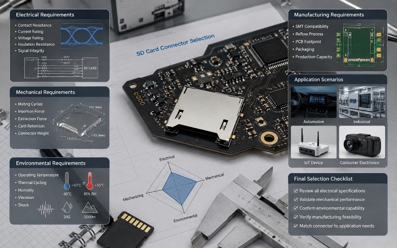
A better selection process evaluates five major categories:
Selection Factor Key Engineering Question
Card Format Standard SD or micro SD?
Mechanical Design Push-push, push-pull, or hinged?
PCB Integration What are the available height and footprint?
Environment What temperature, vibration, shock, humidity, or contamination
will occur?
Electrical Performance What level of contact stability and signal integrity is required?
The same SD card format can therefore require very different connector designs in a consumer product and an automotive controller.
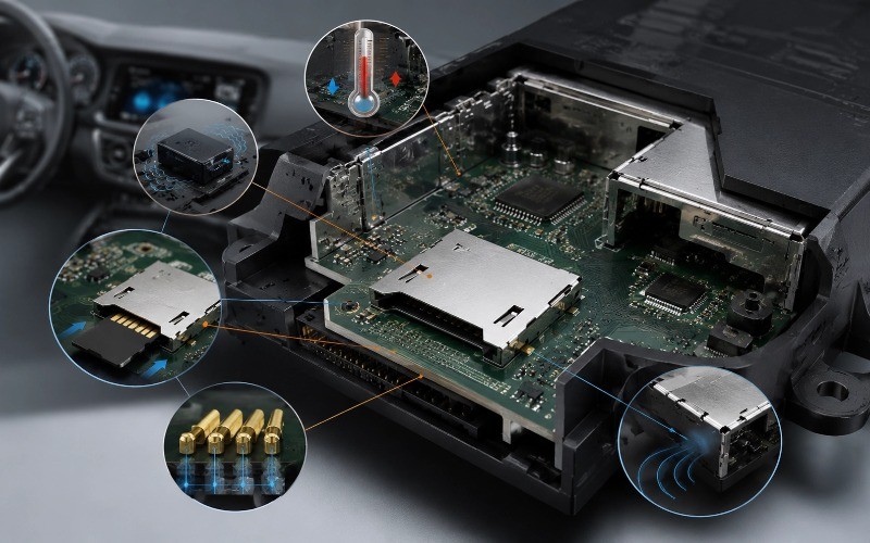
3. SD Card Connectors for Automotive Applications
Automotive electronics create significantly more demanding conditions than many consumer products.
An SD Card Connector used in a vehicle may be exposed to:
Continuous vibration
Mechanical shock
Temperature variation
Thermal cycling
Electromagnetic interference
Frequent service or card replacement
Limited installation space
Amphenol, for example, describes its SD Memory Card Connector for car multimedia applications as a top-mount solution designed for dashboard and vehicular entertainment applications, with emphasis on durability, shock, vibration, high-temperature operation, shielding, and write protection.
3.1 Key Requirements for Automotive SD Card Connectors
Vibration and Shock Resistance
A connector that works reliably on a laboratory bench may not perform the same way inside a moving vehicle
Vibration can cause:
Contact instability
Card movement
Mechanical fatigue
Intermittent electrical connections
Therefore, automotive designs should evaluate the connector's card retention, contact structure, housing rigidity, and mechanical support.
Temperature Performance
Automotive electronic systems can experience substantial temperature variation.
Engineers should evaluate:
Operating temperature range
Housing material temperature capability
Contact stability across temperature changes
Solder joint reliability
Dimensional changes caused by thermal cycling
Secure Card Retention
Card movement can be especially problematic in vibration-intensive environments.
The SD Card Connector should maintain consistent card positioning and contact force during normal vehicle operation
Shielding and EMI Considerations
Automotive electronics contain numerous sources of electrical noise.
Where electromagnetic compatibility is a concern, a shielded SD Card Connector can be considered as part of the overall system-level EMI strategy.
Recommended Automotive SD Card Connector Design Priorities Vibration resistance → Card retention → Temperature performance → Mechanical durability → Shielding → Electrical stability
4. SD Card Connectors for Industrial Equipment
Industrial electronics often operate continuously and may be installed in locations where maintenance is difficult.
Typical applications include:
Industrial controllers
PLC-related equipment
HMIs
Data loggers
Measurement equipment
Industrial computers
Factory automation systems
Monitoring equipment
For these products, connector reliability can become a system-level consideration.
4.1 Durability and Mating Cycles
If a memory card is regularly removed for data transfer, maintenance, firmware updates, or configuration, the connector's mating-cycle capability becomes important.
Engineers should consider:
Expected card insertion/removal frequency
Contact wear
Contact force retention
Ejection mechanism durability
Housing mechanical strength
The goal is not simply to maximize the theoretical number of cycles. The connector should be selected according to the actual service profile of the product.
4.2 Environmental Stability
Industrial systems may experience:
Wide temperature variation
Vibration
Mechanical shock
Dust
Humidity
Continuous operation
An industrial SD Card Connector should therefore be evaluated based on the complete environmental specification rather than one isolated parameter.
4.3 Reliable Electrical Contact
Stable contact resistance is particularly important when the SD interface is used for frequent data transfer.
Potential failure modes include:
Intermittent contact
Contact oxidation
Terminal deformation
Mechanical misalignment
Solder-joint failure
Connector material, terminal geometry, plating, housing design, and manufacturing consistency all contribute to long-term performance.
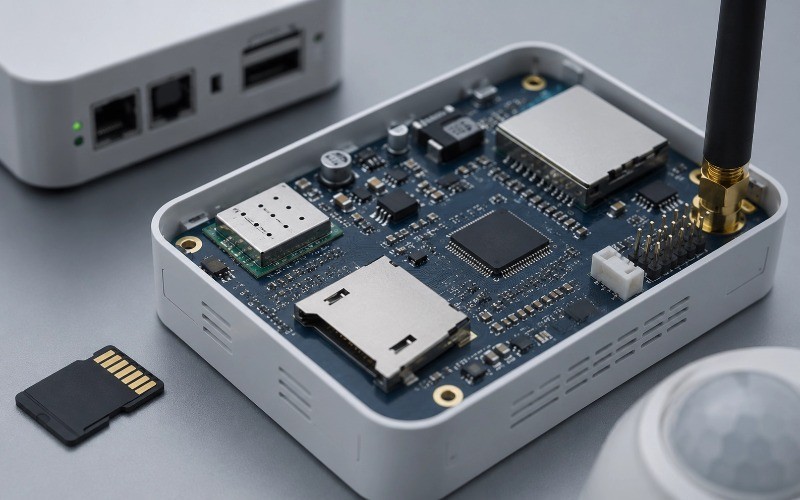
5. SD Card Connectors for IoT Devices
IoT products introduce a different set of design constraints.
Many IoT devices are:
Compact
Battery-powered
Space-constrained
Installed remotely
Designed for long service intervals
Connected to sensors or wireless networks
Common applications include:
IoT gateways
Smart meters
Security cameras
Remote monitoring equipment
Edge devices
Industrial IoT controllers
Smart home devices
5.1 Size and PCB Space
For compact IoT products, connector height and PCB footprint can be critical.
A micro SD connector may be preferable where board space is limited.
Engineers should evaluate:
Connector height
Overall footprint
Card insertion direction
PCB keep-out area
Component clearance
Housing configuration
5.2 Data Reliability
IoT devices may store:
Sensor data
Event logs
Video
Firmware
Configuration files
Local databases
An unstable SD Card Connector can therefore lead to intermittent data access or system-level failures.
Connector selection should consider contact stability and the electrical requirements of the complete SD interface.
5.3 Remote Deployment
When an IoT device is installed in a difficult-to-access location, connector reliability becomes even more important.
For such products, engineers should consider whether the connector design can maintain stable performance throughout the intended product life without frequent service.
6. SD Card Connectors for Consumer Electronics
Consumer electronics often place greater emphasis on:
Compactness
Product appearance
User experience
Cost efficiency
Easy card insertion/removal
High-volume manufacturability
Typical applications include:
Digital cameras
Portable media devices
Tablets
Consumer computers
Gaming equipment
Smart home products
Personal electronics
6.1 Low-Profile Design
A low-profile SD Card Connector can help product designers reduce the thickness of the final enclosure.
This becomes particularly important for:
Portable devices
Slim electronics
Compact embedded systems
6.2 User-Friendly Card Insertion
For consumer products, the card insertion mechanism directly affects the user's experience
Common mechanisms include:
Push-Push
The card is inserted and locked by pushing it into the connector. A second push releases the card.
Push-Pull
The user pushes the card into position and pulls it out directly.
Hinged / Flip
The card is positioned in a hinged structure and secured mechanically.
The best choice depends on the product's available space, user interaction, card retention requirements, and expected usage conditions.
6.3 High-Volume Manufacturing
For mass-produced consumer electronics, the connector should also be compatible with the manufacturer's assembly process.
Relevant considerations may include:
SMT compatibility
PCB footprint
Pick-and-place considerations
Reflow process compatibility
Packaging
Dimensional consistency
Production capacity
7. SD Card Connector Selection Matrix by Application
The following matrix provides a practical starting point for engineers.
| Application | Primary Challenge | Key Connector Requirements | Typical Design Direction |
| Automotive | Vibration, shock, temperature | Strong retention, durable contacts, environmental stability, shielding where required | Robust SD connector |
| Industrial | Long service life and harsh conditions | Durability, stable contact, temperature resistance, mechanical strength | Rugged SD connector |
IoT | Space and remote deployment | Compact size, low profile,reliable contact, efficient PCB integration | MicroSD / low-profile design |
| Consumer Electronics | Size, usability, cost | Compact footprint, user-friendly insertion, manufacturability | Low-profile / push-push design |
Security Equipment | Continuous data storage | Stable transmission, mechanical strength, reliable card retention | High-reliability SD/microSD |
Data Logger | Repeated data access | Reliable contacts, appropriate mating life, environmental stability | Durable SD connector |
8. Which SD Card Connector Design Should You Choose?
The correct SD Card Connector configuration depends on several interacting factors.
Standard SD vs. Micro SD
Choose the card format based on the system architecture and physical space.
Standard SD
Can be appropriate where:
Larger card access is preferred
Mechanical handling is important
PCB space is available
Industrial or equipment-level access is required
Micro SD
Can be appropriate where:
PCB space is restricted
Device size is a major design constraint
The application requires a compact removable storage interface
Push-Push vs. Push-Pull vs. Hinged
Push-Push
Consider when:
User access is frequent
A clean external interface is required
Card retention is important
Push-Pull
Consider when:
A straightforward mechanical structure is preferred
Product space allows direct card removal
Hinged
Consider when:
Additional mechanical retention is useful
Vibration or shock is a concern
The product requires controlled card positioning
The appropriate mechanism should always be evaluated alongside enclosure design and the expected operating environment.
9. Electrical and Mechanical Parameters Engineers Should Evaluate
Selecting an SD Card Connector requires more than checking physical compatibility.
Electrical Parameters
Consider:
Contact resistance
Current rating
Voltage rating
Insulation resistance
Dielectric withstand
Signal integrity requirements
High-speed interface considerations
For higher-speed SD interfaces, PCB routing, connector geometry, contact design, grounding, and shielding can all influence system performance
Mechanical Parameters
Evaluate:
Mating cycles
Insertion force
Extraction force
Card retention
Contact force
Housing strength
Connector dimensions
Connector height
Environmental Parameters
Consider:
Operating temperature
Thermal cycling
Humidity
Vibration
Mechanical shock
Corrosion exposure
Manufacturing Parameters
Don't overlook:
SMT compatibility
PCB footprint
Reflow process
Component placement
Packaging
Production volume
Dimensional tolerances
Dust or contamination
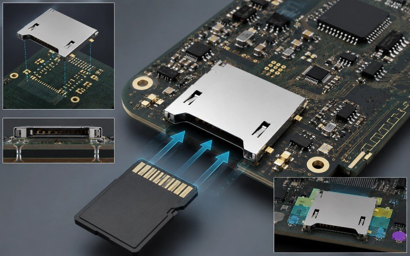
10. How PCB Design Influences SD Card Connector Reliability
An excellent connector can still perform poorly if it is incorrectly integrated into the PCB.
Engineers should verify:
Connector Footprint
Always follow the connector manufacturer's recommended PCB footprint.
Incorrect pad dimensions can cause:
Solder bridging
Insufficient solder joints
Mechanical weakness
Alignment problems
Connector Placement
The connector should be positioned with consideration for:
Card insertion direction
Mechanical clearance
Housing constraints
Adjacent components
Service access
High-Speed Signal Routing
For high-speed applications, designers should pay attention to:
Trace length
Impedance
Signal discontinuities
Crosstalk
Ground reference
Via usage
Mechanical Reinforcement
The PCB should be capable of handling the mechanical force generated when users insert and remove SD cards.
For applications with frequent card access, mechanical support should be considered as part of the complete connector-PCB system.
11. Why Connector Manufacturing Quality Matters
SD Card Connector reliability does not depend only on the final assembly.
It starts with:
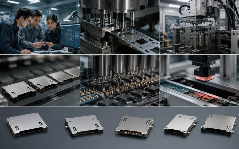
Material → Tooling → Stamping → Injection Molding → Plating → Assembly → Inspection → Qualification
Small variations in terminal geometry, housing dimensions, plating, or assembly alignment can affect contact stability and mechanical performance.
This is particularly important when the same connector design is produced at high volume.
Engineers evaluating an SD Card Connector supplier should therefore ask:
What materials are used for contacts and housing?
How is terminal geometry controlled?
What plating process is used?
How are dimensions inspected?
What reliability tests are available?
Can the supplier support customized dimensions?
Can the supplier provide engineering samples?
Can production scale from prototype to mass production?
12. Why Choose MOARCONN for SD Card Connector Solutions?
For OEMs and product developers, selecting the right SD Card Connector is only one part of the project. The supplier's ability to support customization, tooling, prototyping, production, and quality control can be equally important.
MOARCONN focuses on card connector R&D, manufacturing, sales, and service, with more than 20 years of experience in card connector manufacturing. Its product scope includes SD Card Connectors, Micro SD Card Connectors, SIM Card Connectors, and Smart Card Connectors.
Application-Focused Connector Development
MOARCONN's product and application portfolio covers areas including:
Industrial intelligent equipment
Vehicle electronic equipment
Security monitoring equipment
Consumer electronics
Smart home
Communication equipment
Medical equipment
Aerospace applications
This application breadth allows SD Card Connector development to be considered from both product-design and manufacturing perspectives.
Custom SD Card Connector Development
Not every project can use an off-the-shelf connector.
MOARCONN supports customized connector development, including requirements confirmation, quotation, product design, mold and fixture design, parts production, sample making, trial production, and mass production.
This development process is particularly useful when a customer requires a customized:
Connector height
Housing configuration
Pin arrangement
Mounting structure
Mechanical interface
Card retention solution
PCB footprint
MOARCONN's website states that it has successfully developed more than 1,200 unique connector solutions and highlights SD/micro SD-related customization cases, including a Micro SD card holder connector for security monitoring equipment and an SD card holder connector developed for computer applications.
13. MOARCONN's SD Card Connector Development Process
For a customized SD Card Connector project, an application-driven development process can help reduce design risk.
Step 1: Requirements Confirmation
Define:
Card format
Application
PCB constraints
Dimensions
Mounting method
Operating environment
Electrical requirements
Expected mating cycles
Step 2: Product Evaluation and Quotation
Review the technical requirements and determine the appropriate development route.
Step 3: Product Design
Develop the connector structure according to the mechanical, electrical, and application requirements.
Step 4: Mold and Fixture Design
Create the tooling required for the customized connector.
Step 5: Parts Production
Produce precision connector components.
Step 6: Sample Making
Build engineering samples for evaluation.
Step 7: Trial Production
Validate the manufacturing process before volume production.
Step 8: Mass Production
Scale the validated connector design into production.
MOARCONN publicly describes this eight-stage customization process from requirements confirmation through mass production.
14. SD Card Connector Selection Checklist for Engineers
Before approving an SD Card Connector for production, review the following:
Card Compatibility
Standard SD or micro SD identified
Required card type confirmed
Host interface requirements confirmed
Mechanical Design
Push-push / push-pull / hinged mechanism selected
Connector height confirmed
PCB footprint verified
Card retention evaluated
Insertion and extraction requirements confirmed
Electrical Performance
Contact resistance reviewed
Current and voltage requirements verified
High-speed signal requirements considered
Grounding and shielding strategy reviewed
Environmental Reliability
Operating temperature confirmed
Vibration requirements defined
Shock requirements defined
Humidity/environmental exposure reviewed
Corrosion considerations evaluated
Manufacturing
PCB assembly process confirmed
SMT/reflow compatibility verified
Tooling requirements reviewed
Sample validation completed
Reliability testing completed
Production capacity confirmed
15. Final Takeaway: Match the SD Card Connector to the Application
There is no single SD Card Connector that is ideal for every electronic product.
The correct design depends on the relationship between:
Application → Environment → Mechanical Requirements → Electrical Requirements → PCB Constraints → Manufacturing Requirements
For automotive electronics, vibration, shock, temperature, retention, and shielding may dominate the selection process.
For industrial equipment, durability, environmental stability, and long service life may be more important.
For IoT devices, compact dimensions, low-profile construction, PCB efficiency, and reliable data access can become key requirements.
For consumer electronics, size, user experience, card accessibility, cost, and high-volume manufacturing may have greater influence.
The most effective connector selection process therefore starts with the application—not with a generic product catalog.
For engineers and OEMs requiring standard or customized SD Card Connector solutions, MOARCONN provides SD and Micro SD card connector development and manufacturing, together with customization support from product design and tooling through sampling, trial production, and mass production.
Need help selecting an SD Card Connector for your application?
Share your card type, PCB dimensions, mounting requirements, operating environment, and expected production volume with the MOARCONN engineering team to identify a suitable connector configuration.