Why SD Card Connectors Fail in High-Temperature and High-Vibration Environments: An Engineer’s Guide to Contact Reliability
- Share
- publisher
- MOARCONN
- Issue Time
- Oct 9,2026
Summary
Discover why SD card connectors fail under heat and vibration, and learn how to improve contact reliability and durability.
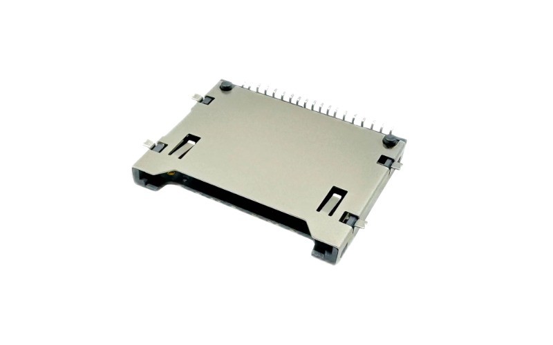
Why SD Card Connectors Fail in High-Temperature and High-Vibration Environments: An Engineer’s Guide to Contact Reliability
An Engineer’s Notebook by Moarconn
SD card connectors are small components, but their reliability can have a direct impact on the performance of industrial controllers, automotive electronics, security cameras, data loggers, and embedded systems.
In high-temperature and high-vibration environments, intermittent card detection, unexpected disconnections, and unstable data transfer may occur even when a connector works normally during initial inspection.
The underlying problem is not always the SD card itself. It may originate from the connector’s electrical contact interface, card retention mechanism, mounting structure, PCB solder joints, or a combination of these factors.
This engineering guide explains why SD card connectors fail under combined environmental stress, how to investigate the root cause, and what engineers should evaluate when selecting or customizing an SD card connector.
1. Why SD Card Connector Reliability Matters in Harsh Environments
An SD card connector provides both an electrical interface and a mechanical interface. Its contacts must maintain electrical continuity while the card is inserted, retained, removed, and exposed to the operating conditions of the finished product.
In demanding applications, including automotive electronics, industrial control equipment, surveillance systems, and embedded data recorders, the connector may experience:
Repeated temperature changes.
Continuous or intermittent vibration.
Mechanical shock during transportation or operation.
Repeated card insertion and removal.
Dust, humidity, or other contamination.
Mechanical stress transmitted through the enclosure or PCB.
These conditions can affect contact stability, card retention, terminal elasticity, solder joints, and the mechanical structure of the socket.
A connector that performs well in a stable indoor environment may require a different design approach when installed in a compact enclosure exposed to substantial temperature changes and vibration.
Engineering takeaway: Connector reliability should be evaluated against the actual operating environment, expected service life, and mechanical integration of the complete product—not only the connector’s nominal temperature rating.
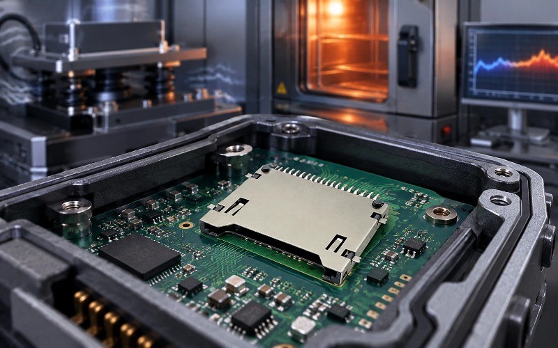
2. Five Common Failure Mechanisms in SD Card Connectors
Understanding the failure mechanism is the first step toward selecting an effective corrective action. Different symptoms can have different causes, so engineers should avoid assuming that every intermittent connection is caused by worn contacts.
2.1 Fretting Corrosion and Contact Wear
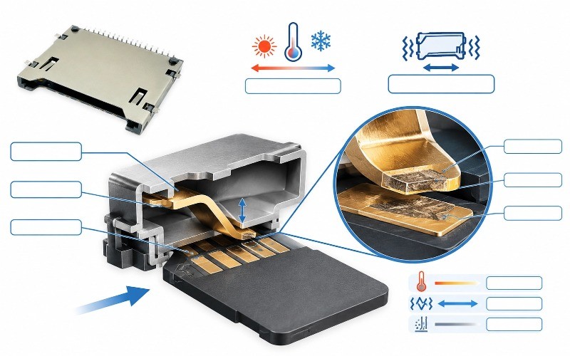
Fretting corrosion can occur when two contacting surfaces undergo small, repeated relative movements. In electrical connectors, this movement may damage the contact plating and generate wear debris.
Depending on the contact materials, plating system, contact force, atmosphere, and movement conditions, surface oxidation and debris can increase contact resistance or make electrical continuity unstable.
Potential contributing factors include:
Vibration-induced micro-motion.
Repeated mating and unmating.
Insufficient or poorly maintained contact force.
Inappropriate contact material or plating for the application.
Contamination at the contact interface.
The result may be intermittent electrical contact, particularly when the equipment is operating under vibration.
What engineers should check: Inspect the contact surfaces for wear or contamination, measure contact resistance using an appropriate method, and compare the results before and after the relevant environmental tests.
2.2 Contact Force Degradation
The contact terminals inside an SD card connector use spring behavior to establish and maintain electrical contact with the card.
Contact force can be affected by terminal geometry, material properties, manufacturing tolerances, operating temperature, and long-term mechanical loading.
At elevated temperatures, some materials may experience reduced mechanical strength or stress relaxation. The actual effect depends on the material, temperature, duration, and design.
If the contact force becomes insufficient, the interface may become more sensitive to vibration, surface films, and dimensional variation.
What engineers should check: Review the terminal design, material specifications, contact geometry, and applicable temperature limits. Where practical, evaluate contact force and electrical resistance before and after thermal exposure.
2.3 Thermal Expansion and Dimensional Changes
An SD card connector typically contains multiple materials, such as metal terminals, a metal shell, and a polymer housing.
These materials may expand or contract by different amounts as temperature changes. The resulting dimensional variation can influence contact geometry, card alignment, locking behavior, and mounting stress.
Thermal cycling may also reveal weaknesses in the PCB assembly, solder joints, or enclosure integration.
What engineers should check:
The connector’s specified operating temperature range.
Housing and terminal material compatibility.
Mechanical clearance and card alignment across the intended temperature range.
PCB mounting and enclosure tolerances.
Electrical and mechanical performance after thermal cycling.
A high maximum operating temperature alone does not establish that a connector will remain reliable under every combination of heat, vibration, and mechanical loading
2.4 Card Retention or Ejection Mechanism Problems
The SD card mechanism is responsible for guiding, retaining, and, depending on the design, releasing the card.
Push-push mechanisms commonly use a spring and a latching or cam arrangement to retain and release the card through successive pushes. Push-pull mechanisms use a different insertion and removal approach, while hinged designs secure the card through a movable cover or frame.
Each mechanism has its own structural requirements and potential wear points.
Under vibration or shock, inadequate card retention, poor alignment, excessive clearance, or mechanical wear may contribute to card movement or dislodgement.
What engineers should check:
Whether the card is fully seated.
Whether the locking and release functions operate consistently.
Whether card retention meets the application’s requirements.
Whether the connector is adequately supported by the PCB and enclosure.
Whether repeated operation changes the mechanism’s behavior.
The best SD card mechanism depends on the application. No single mechanism should be assumed to be universally superior for every environment.
2.5 PCB Solder Joint or Mounting Structure Failure
Not every SD card connection failure originates at the contact interface.
Insertion and removal forces, enclosure loads, vibration, and mechanical shock can also stress solder joints, shell anchors, mounting tabs, and PCB pads.
A connector that moves relative to the PCB may develop cracked solder joints or damaged pads, causing symptoms that resemble contact failure.
What engineers should check:
Solder joint quality and assembly consistency.
Shell anchors and mechanical mounting features.
PCB support near the connector.
Local board deformation and stress concentration.
The relationship between connector movement and electrical interruptions.
A reliable root-cause investigation distinguishes contact-interface degradation from PCB assembly or structural failure before changing the connector design.
3. How High Temperature and Vibration Work Together
Temperature and vibration are often treated as separate qualification conditions. However, in actual equipment, they may occur simultaneously.
Temperature changes can alter material dimensions and mechanical properties. Vibration can introduce repeated micro-motion at contact interfaces and stress the connector’s mounting structure. When these effects occur together, a weakness that is difficult to detect under a single test condition may become more apparent.
Consider the following engineering sequence:
1.Temperature changes alter the dimensions or mechanical behavior of the connector materials.
2.Vibration produces relative movement at susceptible contact interfaces or mounting points.
3.Repeated movement may damage plating or generate wear debris.
4.Surface degradation may cause contact resistance to rise or become unstable.
5.If electrical continuity is interrupted during operation, the host device may report card detection errors or communication failures.
This sequence is a possible failure pathway, not a universal outcome. The actual mechanism must be confirmed through inspection and testing.
The system-level consequences also depend on the host design, interface behavior, firmware, and data-handling strategy. A connector problem can contribute to interrupted data transfers, but data corruption should not automatically be attributed to the connector without further diagnosis.
Why Combined-Stress Testing Matters
A connector may pass an initial electrical inspection and still exhibit intermittent problems under dynamic conditions.
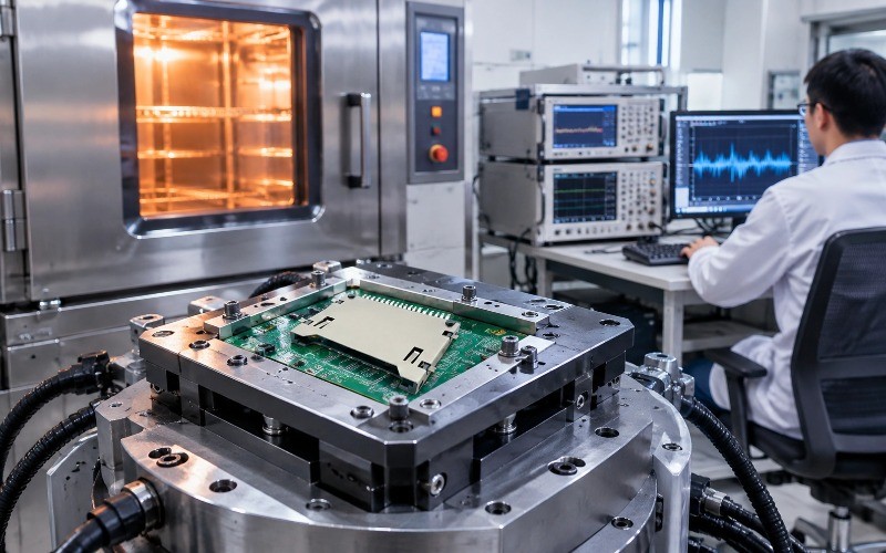
For demanding applications, engineers should consider whether separate temperature and vibration tests adequately represent the intended operating profile. Depending on the risk assessment, sequential or combined-stress testing may provide more useful evidence.
Testing should reflect the product’s actual temperature range, vibration spectrum, mounting configuration, service life, and applicable qualification requirements.
4. How to Diagnose an Intermittent SD Card Connection Failure
An effective investigation begins by documenting the failure conditions rather than immediately replacing the connector.
Step 1: Reproduce the Failure
Record the conditions under which the fault occurs:
Ambient and local operating temperature.
Vibration or shock conditions.
Card insertion and removal history.
Whether the fault occurs during startup, recording, reading, or writing.
Whether the failure follows the connector, card, or host device.
Repeatability helps narrow the possible causes.
Step 2: Inspect the Card and Connector
Check for visible contamination, damaged contact surfaces, bent terminals, incomplete insertion, worn locking features, and mechanical movement.
Inspect the PCB mounting area and solder joints where appropriate. Visual inspection is useful but cannot rule out every electrical or mechanical defect.
Step 3: Measure Electrical Performance
Measure contact resistance and continuity using a suitable test method and the relevant product requirements.
Where intermittent failures are suspected, dynamic monitoring during vibration or other relevant stress conditions may be more informative than a single resistance measurement taken after testing.
Ensure that the measurement setup, wiring, and test fixture do not introduce misleading resistance or mechanical effects.
Step 4: Evaluate the Mechanism and Mounting Structure
Check whether the SD card mechanism retains and releases the card consistently. Examine the shell anchors, mounting tabs, solder joints, and nearby PCB area for evidence of movement or damage.
Do not assume that changing the contact plating will solve a problem caused by inadequate PCB support or a worn locking mechanism.
Step 5: Confirm the Root Cause
Compare the observed symptoms, inspection findings, and measurement results.
Where possible, verify the proposed corrective action using representative samples and the same relevant operating conditions that produced the original failure.
Engineer’s Troubleshooting Table
| Observed symptom | Possible causes | Recommended investigation |
| Intermittent card detection | Contact instability, incomplete insertion, card-detect switch issue, solder joint failure | Monitor continuity and inspect the card-detect and mounting interfaces |
Connection loss during vibration | Fretting, card movement, weak retention, structural looseness | Conduct relevant vibration testing with electrical monitoring |
Failure after thermal cycling | Dimensional changes, contact-force changes, solder or housing issues | Compare pre- and post-test electrical and mechanical measurements |
Increasing contact resistance | Contact wear, contamination, oxidation, insufficient contact force | Inspect contact surfaces and measure resistance using a controlled method |
Card does not lock or eject consistently | Mechanism wear, misalignment, dimensional interference | Inspect the mechanism and verify operation over representative cycles |
These are diagnostic starting points, not definitive failure diagnoses. Final conclusions should be based on product-specific evidence.
5. Design Strategies to Improve SD Card Connector Contact Reliability
Once the failure mechanism is understood, engineers can evaluate targeted design changes.
5.1 Optimize Contact Geometry and Spring Behavior
Contact geometry, terminal material, and spring characteristics influence the force and stability of the electrical interface.
A suitable design should maintain the required contact performance across the intended operating conditions while controlling insertion force, wear, and dimensional tolerances.
Potential design considerations include:
Contact shape and working deflection.
Normal force and contact alignment.
Terminal material and stress-relaxation behavior.
Manufacturing tolerances.
Contact performance after relevant environmental exposure.
Higher contact force is not automatically better. Excessive force may increase insertion effort and wear, so the design must balance electrical stability with mechanical durability.
5.2 Select Contact Materials and Plating for the Application
Contact material and plating selection should consider conductivity, wear, corrosion exposure, mating frequency, and the required service life.
Gold plating is used in many electrical contact applications because of its corrosion-resistant surface properties, but its performance depends on the plating system, thickness, underlying materials, contact mechanics, and environment.
Engineers should review the actual component specification rather than assuming that a particular plating material or thickness guarantees reliability.
5.3 Improve Housing, Retention, and Mounting
Mechanical reliability depends on the connector, PCB, card, and enclosure working together.
Potential design improvements include:
Appropriate card retention and locking features.
Adequate shell anchoring and mounting support.
Suitable housing material for the operating temperature.
Controlled mechanical clearance and alignment.
Reduced stress concentration around solder joints.
Proper enclosure support and card access.
For severe vibration conditions, the complete assembly should be assessed rather than relying solely on the connector’s standalone mechanical characteristics.
5.4 Choose the Right SD Card Mechanism
Different mechanisms address different usability and integration requirements.
Push-push: Useful when convenient insertion and spring-assisted ejection are required. The latching and cam mechanism should be evaluated for wear and reliable operation.
Push-pull: May offer a simpler mechanical arrangement, depending on the design. Engineers should assess accessibility, retention, and the risk of unintended card movement.
Hinged: Can provide a securing cover or frame. The hinge, locking feature, and available installation space should be assessed.
The selection should consider card replacement frequency, enclosure clearance, serviceability, vibration, and retention requirements.
Moarconn’s product range includes SD card connectors with different ejector types and mounting configurations. Engineers can use these options as a starting point when evaluating a connector for a new design or reviewing a component that has failed in service.
5.5 Review PCB Layout and Assembly
Even a well-designed connector may underperform if its PCB integration is inadequate.
Before releasing a design, review:
The recommended PCB footprint and soldering conditions.
Mounting tabs and mechanical anchor points.
Local board stiffness and enclosure support.
Card insertion and removal access.
Signal routing, grounding, and shielding where relevant.
Assembly tolerances and inspection requirements.
For high-speed interfaces, electrical signal integrity should be evaluated separately from mechanical contact reliability. Both may affect system performance, but they require different diagnostic methods.
6. How to Validate SD Card Connectors Before Mass Production
Reliability validation should be based on the intended application, applicable specifications, and the risks identified during design.
A practical qualification plan may include the following tests.
Contact Resistance and Electrical Continuity
Measure the initial electrical performance and compare it with results after relevant environmental and mechanical tests.
Where intermittent faults are a concern, monitor continuity during the stress test if the equipment and measurement method permit it.
Temperature Exposure and Thermal Cycling
Verify that the connector and its assembled interfaces remain within their specified performance requirements over the intended temperature profile.
Consider dimensional changes, material behavior, contact performance, and solder joint integrity.
Vibration and Mechanical Shock
Use representative mounting conditions and application-relevant test profiles.
Monitor electrical continuity where appropriate, and inspect the connector, card retention mechanism, shell anchors, and PCB assembly after testing.
Mating Cycle and Mechanism Durability
Evaluate the required insertion and removal life, insertion and withdrawal forces, locking consistency, and card retention performance.
The specified number of mating cycles should be based on the component specification and the product’s expected service requirements.
Post-Test Inspection and Failure Analysis
Record electrical measurements, visible wear, mechanical damage, and any changes in mechanism operation.
A useful qualification report should identify the sample configuration, test conditions, measurement method, acceptance criteria, observed failures, and corrective actions.
Applicable standards may help define the test method, but engineers must verify the relevant standard, revision, severity level, and acceptance criteria for the specific connector and end application.
Important: Do not assume that passing an individual temperature test or vibration test proves that a connector will pass every combined environmental condition. Qualification results apply to the tested configuration and conditions.
7. When Should Engineers Consider Custom SD Card Connectors?
Standard catalog components can be suitable for many applications. However, a custom SD card connector may be worth evaluating when a standard design cannot adequately meet the product’s mechanical, electrical, environmental, or integration requirements.
Typical triggers include:
A restricted PCB footprint or maximum connector height.
A non-standard card insertion direction.
Specific card retention or ejection behavior.
Application-specific temperature or vibration requirements.
Different mounting or shell reinforcement needs.
A need to review terminal geometry or contact plating.
Integration constraints within a compact enclosure.
Customization should begin with measurable requirements rather than a general request for a “more reliable” connector.
For example, an engineer experiencing intermittent card detection in a vibrating data logger should first identify whether the root cause is contact degradation, card movement, a card-detect switch, or a PCB mounting problem. The proposed custom design can then target the confirmed issue.
How Moarconn Supports Custom Card Connector Development
Moarconn specializes in the research, development, and manufacturing of precision card socket connectors, including SD card connectors, Micro SD card connectors, SIM card connectors, and smart card connectors.
According to the company’s published website, Moarconn has more than 20 years of connector-related experience and supports customized development, precision mold work, and connector application engineering. The company also describes a development process that covers requirements confirmation, design, tooling, sample production, trial production, and mass production.
For engineers evaluating an SD card connector for demanding operating conditions, the development discussion can begin with the actual application requirements.
Relevant design inputs include:
SD or microSD card format.
Available PCB footprint and maximum connector height.
Required ejector mechanism.
Operating temperature range.
Vibration and mechanical shock conditions.
Expected insertion and removal cycles.
Electrical interface and performance requirements.
Target production volume and qualification schedule.
Based on these inputs, the engineering team can assess whether an existing configuration is suitable or whether a customized design warrants further evaluation.
Any proposed material, plating, retention, or structural change should be validated against the project’s defined acceptance criteria. Reliability should be demonstrated through relevant design evidence and testing, not assumed from customization alone.
Looking for a custom SD card connector?
Share your drawing, sample, or preliminary specifications with Moarconn to discuss design feasibility and the next steps for your project.