How to Choose the Right SD Card Connector for Your PCB — Engineer’s Selection Guide
- Share
- publisher
- MOARCONN
- Issue Time
- Sep 12,2025
Summary
Choosing the right SD card connector is a balance between electrical, mechanical, and environmental requirements.
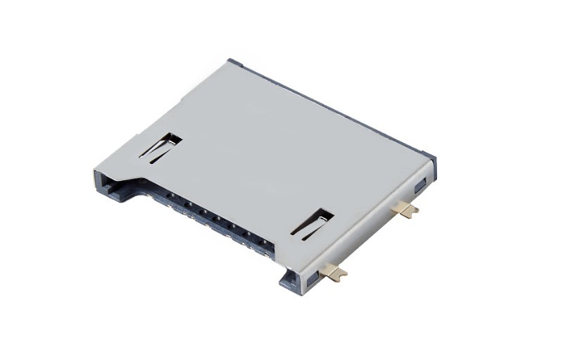
Introduction
Key Factors in Selecting an SD Card Connector
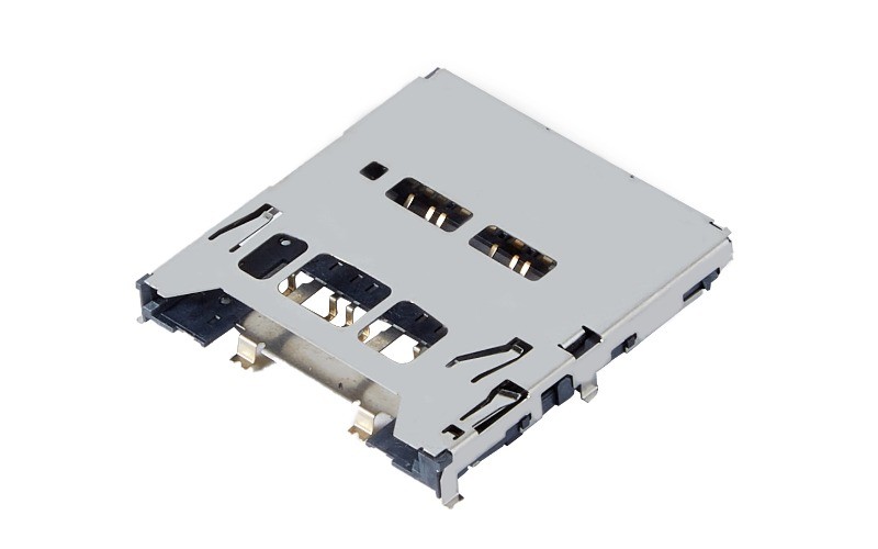
Form Factor and Height Matrix: Choosing Before You Design
Most SD connector problems are decided at the layout stage, not at the connector stage. Before you open the footprint, fix three parameters: card size, mated height, and insertion mechanism. The table below is the practical shortlist rather than a catalogue.
| Card type | Typical body height | Mounting | Common mechanisms | Where it fits |
|---|---|---|---|---|
| Full-size SD / SD 8.0 | 2.94mm push-pull, 3.58mm push-push | SMT, top mount | Push-pull, push-push, hinge | Cameras, dash cams, industrial terminals, automotive recorders |
| microSD / microSD Express | 1.28mm to 1.60mm | SMT, top or reverse mount | Push-pull, push-push, hinge, tray | Phones, wearables, drones, IoT gateways, body cameras |
| SD with write-protect switch | 3.20mm and up | SMT | Push-push, hinge | Data loggers, medical recorders, test equipment |
Two rules of thumb survive most projects. First, the taller the body, the more room the eject mechanism has, so push-push is easier to make reliable at 3.5mm than at 1.3mm. Second, every 0.1mm you remove from the height has to come out of somewhere — usually terminal wipe length or housing wall thickness — so treat sub-1.3mm parts as a different design problem, not a smaller version of the same one.
MOARCONN currently runs 141 card socket models across 13 series, which means most height and mechanism combinations already exist as a tool rather than needing a new one. Ask for the closest three models and compare footprints before you ask for a custom housing.
Top Mount vs Reverse Mount: The Decision That Costs PCB Area
Top mount places the connector on the same side as the rest of the components; the card slot faces the board and the card sits above it. Reverse (bottom) mount puts the connector on the opposite side of the PCB so the card enters from the back of the housing. Reverse mount is what makes a 7mm-thick phone possible: the card occupies the space behind the main board instead of on top of it.
The cost of reverse mount is process, not product. You need a cut-out in the PCB, tighter placement tolerance because the connector is now visible through the housing, and a reflow profile that works for a part hanging over an opening. It also constrains where you can put test points and stiffeners. For industrial and automotive boards, where thickness is rarely the binding constraint, top mount is almost always the better trade.
Whichever side you choose, reserve the keep-out early. A microSD push-push socket needs roughly 15mm x 15mm of board including the card travel, and the card needs a clear path to the housing slot with at least 0.2mm of clearance on each side. Discovering that the card path crosses a shield can is the single most common cause of a late respin.
Pin Count, Card Detect and Write Protect
A full-size SD connector carries nine contacts: CLK, CMD, DAT0 to DAT3, VDD, VSS and a card-detect (CD) contact that is usually a normally-open mechanical switch tied to DAT3 on legacy designs. microSD uses eight contacts in the same electrical arrangement minus the second ground, and adds the detect function through a separate switch in most sockets.
Card detect is not optional in a product that ships to consumers. Without a hardware CD line, the host has to poll the interface to notice insertion, which costs current in sleep states and delays enumeration on wake. With CD, the controller can stay idle until the switch closes and then run a clean initialization sequence. The detect switch is also the part most likely to wear out, so specify its cycle rating separately from the contact rating — they are not the same number on most datasheets.
Write protect only exists on full-size SD. The side switch on the card is read by a second switch inside the connector, and firmware uses it to force read-only mode. If your product writes logs, a write-protect contact is worth the extra pin: it lets a field technician lock a card without pulling it from the slot.
Signal Integrity for UHS-II and SD Express
UHS-I runs the legacy single row of contacts at up to 104MB/s and is forgiving. UHS-II adds a second row of pins for a differential lane and pushes the interface to 312MB/s; SD Express goes further and puts PCIe lanes on the same second row. Both of the faster modes change what the connector has to do: it is no longer a passive part, it is part of the transmission line.
Three layout rules matter most. Route the differential pair with 90Ω differential impedance (roughly 50Ω single-ended) and hold it within ±10%, which usually means a controlled-impedance stack-up and no layer changes under the connector. Keep the stub from the pad to the pair under 2mm; a long stub turns into a resonator at PCIe frequencies and shows up as eye closure that no amount of tuning will fix. Stitch ground between the pair and any adjacent high-speed net, and keep the pair away from the switching regulator that powers the card.
Power delivery deserves the same attention. SD Express cards can draw close to 1.8A in bursts, so the VDD trace needs to be sized for the transient, not the average, and the decoupling has to sit within a few millimetres of the connector pin rather than at the far end of the rail. Ask the connector supplier for the contact resistance figure at the rated current, not just the dry-circuit value.
Insertion Force, Coplanarity and Cycle Life
Insertion and extraction force is where a connector either feels engineered or feels cheap. MOARCONN's internal specification holds 3~25N against a national range of 5~40N: the window is deliberately narrower so that the tenth insertion feels like the first, and so that a user with limited hand strength can still seat the card. If your product is used with gloves — automotive, industrial, outdoor — ask for the upper end of the range, not the lower.
Coplanarity is the specification that decides first-pass solder yield on a thin board. MOARCONN holds terminal coplanarity at ±0.05mm against the ±0.10 mm common in the industry, with full-area solder plane flatness of 0.05mm max. On a 0.8mm board with a 1.28mm socket, a 0.12mm drift across the tails is enough to lift a pad; on a 1.6mm industrial board the same part will pass. Measure it after reflow on your own assembly, not on the bare connector.
Cycle life follows from terminal geometry and plating rather than from the housing. Phosphor bronze terminals plated to at least 0.025µm of gold over nickel hold contact resistance at or below 30mΩ through a 10,000-cycle rating — twice the national requirement — and keep it there between -45°C and 80°C. Thinner plating saves a fraction of a cent and starts to drift once the barrier layer is exposed, especially in humid or sulfur-bearing air.
Prototype vs Mass Production: What to Ask For
The connector is rarely the long-lead item on a new board, but the tooling behind it can be. The questions below are the ones that actually change a schedule.
- Is the part a catalogue model or a new tool? With 141 models across 13 series, a near match usually exists; adapting a housing is weeks faster than a new mold.
- What is the sampling lead time? MOARCONN quotes 7 days for samples and 25 days for a custom development cycle.
- Is there a minimum order? 0 MOQ matters at the prototype stage, when you need 20 pieces and a dimensional report, not a reel.
- Who answers technical questions? Original-factory FAE support within 24 hours is the difference between a two-day fix and a two-week one.
- Are samples retained? MOARCONN keeps samples for 3 years, so a field return can be traced back to its production lot.
Send the RFQ with five attachments and you will get a usable answer in one round: the PCB footprint with pad dimensions, the mated height you have available, the card type and speed mode, the operating temperature range, and the annual volume with your target assembly method. Suppliers who ask for those five are the ones who will also flag the keep-out problem before you cut the board.
SD Card Connector Selection FAQ
Should I specify SD, microSD or SD Express for a new design?
Start from the data rate, not from the card size. If sustained throughput stays under 100MB/s, UHS-I microSD with a single-row connector is the cheapest and most available option. Above that, UHS-II or SD Express is required, and the connector must have the second contact row plus a layout that can carry a controlled-impedance pair. Choosing SD Express hardware for a 30MB/s logger adds cost and layout risk for no benefit.
What is a safe mated height for a slim product?
A 1.28mm microSD push-pull socket is the practical floor for a device that is assembled once and sealed. Below that, terminal wipe length gets short and insertion feel degrades. If the card must be user-accessible, allow 1.5mm to 1.6mm for push-push or hinge mechanisms, and remember that the card path through the housing needs clearance on both sides.
How many mating cycles should I require?
For a sealed consumer device where the card goes in once, 5,000 cycles is already generous. 10,000 cycles — twice the national requirement — is the right number for dash cams, body cameras, test fixtures and any product where the card is swapped weekly. It is also a useful proxy for terminal design and plating quality even when your own duty cycle is low.
Why does my connector pass the datasheet but fail AOI after reflow?
Almost always coplanarity measured on the bare part rather than after assembly, or a stencil and profile that were qualified on a different board thickness. Ask for the coplanarity figure in writing, verify it on your own assembly at the tail end of the reflow panel where warp is worst, and check that the pad geometry matches the supplier's recommendation rather than a generic land pattern.
Why Choose MOARCONN SD Card Connectors?
Conclusion
MOARCONN Quality Anchors
Every MOARCONN card socket connector is validated to 10,000 mating cycles (tested to GB/T 5095.7-1997; over 2× the 3,000–5,000 cycles common in the industry), operates from -45°C to 80°C, and ships with contact resistance ≤30mΩ thanks to ≥0.025µm gold-plated phosphor-bronze terminals. IATF 16949 certified production supports 0 MOQ orders with 7-day sampling and a 25-day development cycle — backed by in-house mold, stamping and injection molding factories and 32 granted patents.