MicroSD and SIM Connectors for Fleet Dash Cams: From Design to Production
- Share
- publisher
- MOARCONN
- Issue Time
- Nov 19,2026
Summary
Follow a fleet dash cam connector from the application brief through design, materials, tooling, pilot production and validation. See how service access, contact behavior and manufacturing evidence shape the decisions.

APPLICATION DESIGN STORY · FLEET VIDEO TELEMATICS
Follow a fleet dash cam connector from the application brief through design, materials, tooling, pilot production and validation. See how service access, contact behavior and manufacturing evidence shape the decisions.
An illustrative application and development plan for hardware engineers and R&D leads. It does not report a completed customer project or vehicle qualification.
Plan your dash cam connector review Start with the drawings and constraints you already have.
How should you choose microSD and SIM connectors for a fleet dash cam?
Choose the microSD interface around local recording and authorized card replacement, and the SIM interface around modem compatibility and controlled access. Compare the complete installed and operating envelope, then validate contact, retention and device behavior under agreed conditions. A mechanism type or catalog speed figure alone does not establish device reliability.
- Mechanical decision
- Include card projection, push-overtravel or hinge opening, and the service cover. Compare the mechanism trade-offs.
- Engineering decision
- Connect structure and material choices to tooling, first articles and pilot-build controls. Follow the development route.
- Evidence decision
- Separate published product information from the reports required for this device. Review the validation checklist.
01 / START WITH THE SERVICE MOMENT
The camera returns to the depot. Who needs to touch which card?
Picture a windshield-mounted camera in a delivery fleet. It records locally during a route and uses a cellular modem to send selected events and status information when coverage is available. At the depot, an authorized technician may need to retrieve a recording or replace the storage card. The subscriber identity card is changed less often and should remain under controlled access.
These are the assumptions for this story, not specifications from an actual customer. The design task is to fit both interfaces into a compact enclosure without making routine storage maintenance disturb the SIM connection.
The overlooked decision comes before connector height: define the service route for each card separately. A convenient external microSD slot and an internally accessed SIM socket can make sense together. They still need a workable enclosure, an agreed service procedure and evidence from the finished assembly.

SYSTEM VIEW / CONCEPTUAL, NOT A PRODUCT SCHEMATIC
Local recording and cellular connectivity are different paths
Capture and compress video
Recording, file management and event handling
Removable local video storage
SIM socket + SIM → subscriber identity
System conditions influence both paths.
The SIM socket connects the identity card to the modem; it does not carry the camera’s cellular radio signal or store the recorded video. A lost upload and a missing local clip therefore need different diagnostic paths.
02 / THE FOUR DESIGN DECISIONS
Choose around access, movement, heat and the recording workload
Easy card removal can conflict with controlled retention
A push-push socket can make a recessed microSD card easier to remove. But the card needs travel beyond its seated position to operate the ejector. A protective cover must not press it into release, and the technician needs room to retrieve it.
A push-pull design avoids the push-again action, but a small enclosure opening may make the card hard to grip. An internally accessed hinged SIM holder is worth comparing when SIM replacement is infrequent; it needs clearance to open and a verifiable locking sequence.
Decide: who replaces each card, with which tool and with the unit powered down or in which controlled state? Verify: run the intended service procedure on an enclosure prototype, including misalignment and accidental pressure. The value is a serviceable unit whose card access has been designed deliberately, rather than discovered after tooling.
A low socket is not the same as a small installed envelope
Nominal mounted height leaves out card projection, eject travel, hinge opening, assembly tolerances and nearby components. A socket that fits on the PCB drawing may still be impossible to operate behind a cover.
Decide: compare the complete card-in, card-out and assembly envelopes against the approved connector drawing. Review PCB support, shell anchors and access to solder joints as part of the same layout. Do not call a replacement “drop-in” until pads, pin mapping, datums and operating clearances have been compared.
Verify: check the tolerance stack and a physical assembled sample, not just nominal CAD. This makes mechanical acceptance explicit before the PCB and enclosure are released.
Road motion and heat need an assembly-level answer
The enclosure mount, PCB flex and card restraint determine how movement reaches the contact interface. Small repeated movement at contacts can cause fretting-related degradation; vibration and temperature variation are documented drivers in connector contact research. A closed hinge or a metal shell, by itself, is not proof of suitable vibration performance.
Decide: define the environment at the installed socket position, including heat from the processor and modem. Compare candidate operating limits, retention geometry, shell anchoring and the available qualification evidence. Reflow tolerance is a manufacturing condition; it is not an operating-temperature rating.
Verify: use the final mounting arrangement and representative cards in agreed thermal and vibration tests. Monitor continuity and device behavior during exposure, then inspect retention and solder joints. Match the profile, duration, axes and acceptance criteria to the device specification; do not borrow an unexplained “automotive-grade” label.
A missing clip is a symptom, not a connector diagnosis
Repeated video writing tests the memory card as well as the socket. The SD Association distinguishes speed classes by minimum sequential access performance under defined conditions. A connector’s advertised interface speed does not establish the card’s sustained write performance, endurance or the recorder’s ability to close a file at power loss.
Decide: specify approved cards for the actual recording workload and evaluate endurance separately from bus capability. Memory-card suppliers such as SanDisk publish endurance-oriented products for repeated recording; that is card evidence, not evidence for a MOARCONN socket or a particular camera.
Verify: reproduce recording gaps while logging card detection, storage errors, supply behavior and software events. Compare known-good cards and assemblies. Test shutdown and restart behavior separately. A connector change cannot fix inadequate power hold-up, worn flash, a filesystem problem or an unsuitable host configuration.
03 / MAKE THE TRADE-OFF VISIBLE
Compare service behavior before choosing a mechanism
These are candidate architectures for evaluation. The names describe mechanisms, not a ranking of reliability.
| Option | When to consider it | The compromise | Evidence before selection |
|---|---|---|---|
| MicroSD / push-push | Recessed card with technician access through a service cover. | Needs push-overtravel and eject space; cover pressure must not release the latch. | Drawing, assembled access trial, latch/retention behavior and powered environmental tests. |
| MicroSD / push-pull | A card edge can be gripped and a straightforward manual removal path is possible. | Grip space and retention must work with the enclosure; simpler operation is not automatic vibration approval. | Card projection, extraction force, enclosure restraint and the intended service-cycle test. |
| SIM / internal hinge | Subscriber card is fitted during assembly or controlled depot service. | Opening the enclosure and hinge needs clearance; closure and locking must be checked. | Card-format match, locked-cover clearance, assembly instructions and continuity under the agreed profile. |
| SIM / external tray | External SIM replacement is a genuine service requirement. | Tray, opening, tool access and any seal become part of the system design. | Tray tolerance, retention, operating sequence and any enclosure ingress test required by the device. |
Working design direction: evaluate a service-accessible microSD socket and a separately controlled SIM interface. Change that direction if the enclosure, service policy or validation evidence points elsewhere.
04 / CONNECT THE DECISION TO REAL PRODUCTS
Two MOARCONN candidates to put on the review table
MOARCONN’s published catalog provides the following starting points. The listed mechanism and height help screen the mechanical concept; they do not establish approval for this illustrative fleet camera.
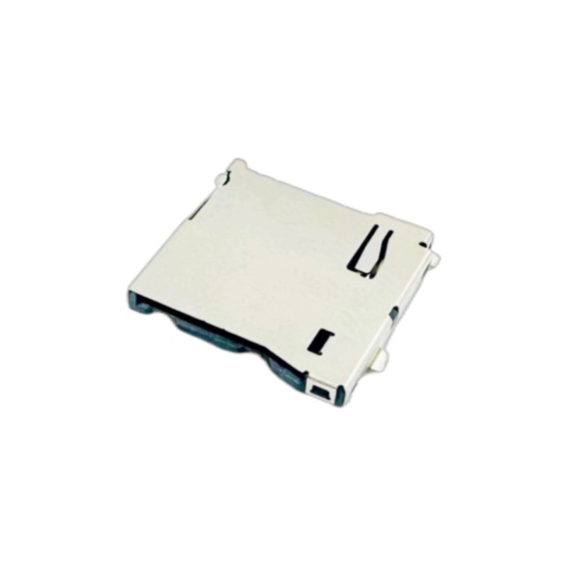
REMOVABLE VIDEO STORAGE
MC185-T1250-40
Published as a Micro SD push-push connector with 1.85 mm height. Consider it when a recessed card needs a press-to-eject service path.
Confirm before sampling: current drawing revision, land pattern, card projection and eject travel, detect-contact arrangement, retention requirements and model-specific thermal/vibration evidence.
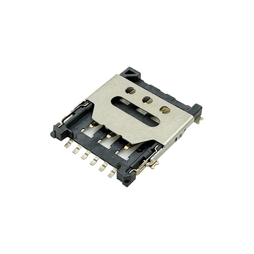
CONTROLLED SIM ACCESS
NS143-T1151-01
Published as a Nano SIM hinged connector with 1.43 mm height. Consider it when the selected SIM format is Nano SIM and internal service access is acceptable.
Confirm before sampling: hinge opening and locking clearance, modem-to-card pin mapping, any card-detect function, assembly process and model-specific qualification evidence.
If the device specification calls for Micro SIM, compare the 1.50 mm hinged Micro SIM product as a separate format decision. Micro SIM and Nano SIM sockets are not interchangeable simply because both provide subscriber identity.
When a standard part does not fit the service envelope
Use a marked-up drawing to show the conflict: height, card access direction, footprint or cover clearance. MOARCONN’s published customization process includes requirements review, design discussion, drawings, tooling, sample assembly and trial production. That provides a route for a feasibility discussion; it does not establish that any requested change is possible or already qualified.
Agree the proposed change, drawing revision, sample scope and validation ownership before development. Review sample-request requirements after confirming the configuration you want to evaluate.
DEVELOPMENT ROUTE / REQUIREMENTS TO PILOT BUILD
How the microSD concept becomes a producible connector
For this illustrative camera, the development brief centers on the removable microSD interface. The SIM access decision remains an enclosure constraint. This is a proposed engineering route, not a claim that either catalog candidate was developed for a named customer or has completed this project.
- Agree the application
- Review design and materials
- Develop tooling
- Evaluate first articles
- Control the pilot build
- Validate and close issues
- Release the agreed configuration
1. Turn the device brief into an agreed specification
The application discussion would start with the camera enclosure, board position and technician’s service sequence. The hardware engineer would define the card format and host-interface mode; the mechanical engineer would mark the seated card, push-overtravel and retrieval envelopes. Purchasing and quality would add the required ordering configuration and documentation.
The team would compare existing products and reference parts before choosing customization. A comparison should identify footprint, contact mapping, card travel, retention and mounting differences. A competitor’s drawing is a reference for evaluation, not evidence that another socket is interchangeable. The review output is a requirements matrix with acceptance conditions and a reason to select a standard part or develop a change.
2. Give the contact spring room to work
The structural engineer would evaluate the contact position and available deflection across the tolerance stack of the card, housing, terminals and shell. More contact force is not automatically a better solution: it can increase insertion load or local stress. Reducing height can also remove working travel. These effects need to be balanced with retention, service access and the allowed assembly envelope.
CAD would establish geometry and interference clearances. Where appropriate, force and deformation analysis would compare alternatives using documented material data, boundary conditions and assumptions. Physical samples would then check those assumptions. The release record should explain the selected geometry, its risks and the measurements needed to confirm it.
3. Choose a material system that can be manufactured
For the insulating base, the review would compare the actual resin grade, molding behavior, dimensional stability and compatibility with the proposed soldering process. A resin family name alone does not establish performance. For terminals, the copper-alloy grade and condition need to balance forming behavior, conductivity, elastic working range and relaxation over the intended conditions. The shell material and forming process must support location and retention.
Contact areas and soldering areas serve different functions, so the drawing should define the required finish system and regions. Material declarations and any supporting reports must match the selected configuration. MOARCONN’s published customization process provides a basis for discussing these choices; feasibility and evidence for the specific change still need agreement.
4. Review the tools as three separate engineering problems
The plastic housing, spring terminals and metal shell need different tooling decisions. An injection-mold review would examine filling, gating, parting lines, flash near the card path, shrinkage and warpage. Terminal stamping and forming would examine strip location, burr direction, contact geometry and springback. Shell tooling would focus on locating features, anchors and the way forming variation affects assembly.
The toolmaker and product engineer would agree which dimensions must be checked by cavity or forming station. Precision machining is one step; repeatable parts require a suitable tool concept, controllable process and a way to measure the features that matter. Tool corrections should be linked to measured variation, not to a visual preference alone.
5. Use first articles to test the design assumptions
First articles would be checked against the approved drawing and assembled with representative cards. Card-path clearance, contact position, latch action, shell fit and solder-foot coplanarity would be examined together. The team would retain cavity or tooling identity where it helps explain differences between samples.
If, for example, insertion behavior changes after reflow, that observation would start an investigation. The team would compare housing dimensions, terminal free height, shell position, assembly conditions and the measured oven profile. It would not immediately call the resin or ejector the root cause. A tooling or process change would be justified by the findings, then followed by checks of both the original symptom and related functions.
6. Translate the drawing into a pilot-build control plan
Before a pilot build, production engineering would turn critical characteristics into practical work and inspection instructions. The plan would connect material identity, molding and forming controls, finishing, assembly sequence, functional checks and packaging. Gauges and measurement methods must be suitable for the dimensions they are intended to control.
The pilot should show how variation behaves across relevant cavities, batches and assembly conditions. A few selected good samples do not establish a repeatable process. The drawing, bill of materials, finish specification, work instructions and inspection criteria must share the approved revision. Material substitution, tool maintenance and process changes then need an agreed review route.
Working around a card-access or footprint conflict? Bring a marked-up drawing to the connector review.
7. Close the engineering loop before release
Design, tooling, materials and production engineers would review unresolved issues against the validation plan below. Each issue needs a recorded observation, supported cause, controlled change and verification of the affected requirements. Where one change influences other functions, the verification scope must include them.
Release would depend on the agreed drawing and specification, satisfactory verification, pilot-build disposition and customer approval where required. The handover should identify the exact configuration, inspection records and traceability requirements. Later feedback belongs in the same controlled change process. This gives the customer a defined acceptance basis and a way to understand future changes.
ENGINEERING BASIS / METHODS AND ACCEPTANCE
Define what “meets the requirement” actually means
A useful development story connects each claimed result to a method, condition and approved limit. The following references help structure the discussion; they are not certifications or pass claims for the products shown here.
| Reference | Use in the development plan | What still needs agreement |
|---|---|---|
| IEC 60512-1:2018 | Framework for connector tests and measurements. | Applicable methods, severity, sequence, sample configuration and permitted performance limits in the detail specification. |
| IEC 60512-2-1:2002 / IEC 60512-3-1:2002 | References for millivolt-level contact resistance and insulation-resistance measurements. | Measurement conditions, points and acceptance limits. Insulation resistance, dielectric testing and operating voltage are different requirements. |
| SD interface specifications | Identify the card and host-interface requirements for the selected mode. | Applicable complete specifications and system verification. Public simplified documents are not a substitute for the full development requirements. |
| UL 94 material testing | Check a required flammability classification for the actual resin grade and relevant thickness. | Whether the project requires it and which material evidence applies. A material rating does not certify the complete connector or device. |
| RoHS restricted substances / REACH supply-chain information | Review the applicable substance restrictions and material documentation. | Current market requirements, applicable limits or exemptions and configuration-specific evidence. A RoHS declaration does not establish universal absence of hazardous substances or cover every REACH obligation. |
The project team should confirm the applicable editions before testing. Final acceptance must refer to the approved product and device specification, rather than an unexplained standard number on a marketing page.
05 / TURN THE CONCEPT INTO EVIDENCE
A validation plan that can explain a pass—or a failure
Freeze the part revision, representative card set, board revision and enclosure configuration before comparing results. Set test conditions and acceptance limits before testing. Record failures as well as passes.
| Check | Why it matters here | Evidence to retain |
|---|---|---|
| Drawing and service fit | The card must seat, eject or unlock without hitting the cover or neighboring parts. | Approved 2D/3D revision, tolerance review and photos/video of the assembled service sequence. |
| PCB and assembly process | Socket alignment, solder attachment and board support affect the installed connection. | Land-pattern review, agreed reflow profile, first-article inspection and joint inspection records. |
| Mechanical retention and service wear | Repeated handling may change operating force, latching or contact behavior. | Agreed cycle sequence with the intended cards; force/retention observations and electrical checks before and after. |
| Temperature at the installed position | Internal heating and environmental exposure must remain within each component’s confirmed limits. | Thermal measurements, operating/storage definitions, agreed exposure sequence and functional records. |
| Vibration and shock in the enclosure | A board-only or static contact check can miss intermittent behavior in the mounted device. | Fixture, mounting position, axes, profile, duration, sample configuration, continuity-monitoring setup and raw event logs. |
| Recording, power interruption and restart | Card performance, supply and software can cause missing files independently of the socket. | Actual video workload, approved card identities, power and storage logs, recovered-file checks and restart results. |
| SIM recognition and recovery | SIM detection/initialization and network reconnection are separate from SD recording. | Modem/card compatibility review, controlled insertion procedure, SIM-status logs and recovery observations. |
06 / WHAT THIS CHANGES FOR THE BUYING TEAM
One agreed selection basis, from development to production
For engineering: release a serviceable design
The output is an approved footprint, full operating envelope and a verification plan that separates socket behavior from card, power and firmware behavior. The target is a defensible design decision, not an unmeasured reliability claim.
For purchasing: quote the configuration that was evaluated
Identify the exact part and drawing revision, agreed material/finish requirements, packaging and documentation. Confirm quotation, sample availability, order conditions and lead time for that configuration. A visually similar alternate should go through the defined comparison and approval process.
For quality and production: retain a repeatable acceptance basis
Carry the agreed assembly checks, inspection criteria and traceability requirements into the pilot build. Define how proposed component changes and field failures are reviewed. This gives each team a shared record of what was selected and why.
ENGINEERING FAQ
Questions a fleet dash cam team should settle early
Is push-push always the best microSD choice for a dash cam?
No. It is useful when a recessed card needs easy ejection. Compare available push travel, cover pressure, card retrieval, retention and service frequency. A push-pull design may be appropriate if the card can be gripped and retained within the enclosure. Validate the chosen assembly.
Can I select the SIM socket by the modem’s cellular data rate?
No. Select the socket for the specified SIM format, electrical pin mapping, mechanical access and operating conditions. The SIM provides subscriber identity to the modem; the cellular data path depends on the modem, RF system and network.
Does a connector’s bus-speed figure prove that video recording will be continuous?
No. Sustained recording also depends on the host interface, PCB, memory card, power and software. Select the card for the recorder’s workload and verify complete recordings under the intended conditions.
Can a hinged SIM connector be treated as vibration-qualified?
No. The locking structure is a selection feature, not a test result. Request evidence for the candidate revision and evaluate it with the intended card, PCB support and enclosure mounting.
Does a card-detect contact make hot removal safe?
No. Detection does not establish power sequencing, modem support or filesystem safety. Define a controlled replacement procedure and verify the hardware and software response. Do not assume that either card may be removed during operation.
What should I send before asking for samples?
Send the card formats, PCB and enclosure drawings, maximum installed envelope, access sequence, operating conditions and any existing part number. Include the planned recording workload and validation requirements. Ask MOARCONN to confirm the candidate revision and sample configuration before ordering a trial.
FROM DESIGN QUESTION TO ENGINEERING REVIEW
Bring your dash cam constraints into a connector review
You can start with an enclosure sketch, an existing part or a defined specification. Include what is known and identify what still needs an engineering decision.
- Application and cards: fleet-camera use, microSD format/interface mode, and the SIM format required by the modem.
- Space and access: PCB and enclosure drawings, installed-height limit, card travel and the intended service sequence.
- Environment and workload: mounting location, operating/storage conditions, recording workload and planned card types.
- Current design: existing part number, approved drawing revision or the conflict you want to resolve.
- Next decision: standard-product comparison, customization feasibility, drawing review or sample evaluation; include project timing and volume assumptions if known.
Suggested inquiry subject:
Fleet dash cam microSD / SIM connector engineering review
Send requirements for engineering review
Use that subject in your message and attach the relevant drawing if available. Ask MOARCONN to confirm the candidate configuration, available documents and proposed next step.
Ready to evaluate samples?
First identify the exact part and drawing revision, intended card, PCB/enclosure fit and the checks you want to perform. Confirm sample configuration, availability and ordering conditions before planning the trial.
Sources and scope
This application design story combines an explicitly illustrative device scenario with published product information and engineering references. No customer results, completed tests or project delivery commitments are asserted. Product sources were reviewed on 18 November 2026; this editorial plan was updated on 19 November 2026. Please confirm the current approved drawing and specification for design-in.
- MOARCONN vehicle electronics applications
- MOARCONN Micro SD push-push product, 1.85 mm
- MOARCONN Nano SIM hinged product, 1.43 mm
- MOARCONN Micro SIM hinged product, 1.50 mm
- MOARCONN customization process
- MOARCONN quality control process
- SD Association: Speed Class
- Morton Antler: Contact Fretting of Electronic Connectors, IEICE (1999)
- SanDisk: High Endurance microSD card datasheet